OSPF Neighbor Exchange Process
Using the Hello protocol, there is a series of exchanges that routers go through in order to establish relationship when OSPF is initilized. I’d like to go through some of this steps using examples from a lab environment, and watching some debug output in the process.
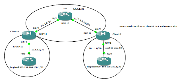
To start, here’s the setup for the exercise:
Figure 1: A simple topology

Dynamips .net Config:


Figure 4: Router A Goes to Init State


Figure 6: Router B in Two-way State


Figure 8: Router B – DR Election


Figure 10: Router A – Slave


Figure 12: Router B – Exchange

Figure 14: Router B: Loading-Full State
To start, here’s the setup for the exercise:
Figure 1: A simple topology
Dynamips .net Config:
# OSPF Neighbor Exchange Lab Topology
autostart = False
ghostios = true
sparsemem = true
[localhost] [[7200]] image = \Program Files\Dynamips\images\C7200-JK.BIN # On Linux / Unix use forward slashes: # image = /opt/7200-images/c7200-jk9o3s-mz.124-7a.image npe = npe-400 ram = 96 ghostios = True[[ROUTER A]] Fa0/0 = B Fa0/0 model = 7200 console = 2001 [[router B]] model = 7200 console = 2002
Down State
Figure 2: Router A – interface added to OSPF- When the router is enabled on the LAN, it starts in the Down state and starts sending out hello packets to multicast address 224.0.0.5.
- When in Down state, it doesn’t mean that the interface or router itself is down. It’s just that it hasn’t received any Hellos from any neighbors.
- When an interface is enabled on OSPF, it starts sending out Hello packets to multicast 224.0.0.5 as seen in the figure above.
- Notice also that after sendnig Hello packets 4 times (40 seconds) and not finding an OSPF neighbor, it takes it upon itself to elect itself as a Designated Router (DR) for that LAN segment.
Init State
- The init state indicates that a router sees HELLO packets from the neighbor, but two-way communication has not been established. A Cisco router includes the Router IDs of all neighbors in the init (or higher) state in the Neighbor field of its HELLO packets. For two-way communication to be established with a neighbor, a router also must see its own Router ID in the Neighbor field of the neighbor’s HELLO packets.
Figure 4: Router A Goes to Init State
- At 4:43:11 PM, Router B’s Fa0/0 is enabled for OSPF. Almost immediately it starts sending out Hello packets.
- Within a few tenths of a second (at 4:43:17) Router A receives a packet from Router B with its database summary.
- Router A also transitions to the Init state, indicating that although it has received something from Router B, nowhere in those packets is Router A’s Router-ID.
- Remember, in order for the relationship two transition to the next level (two-way state), the receiver must receive a Hello from the other neighbor which contains its (Router A’s) own Router ID.
- However, aside from needing to receive its own Router-ID in the neighbor field of the neighbors Hello packet, receiving a DBD from the neighbor also puts the state into a two-way state.
- Looking at the output in figure 4, it confirms that Router A did receive a DBD from Router B.
Two-way State
- In order to attain the 2-way state, a bi-directional communication has to be established between two routers.
- That means that each router has seen the other’s hello packet.
- When the router receiving the hello packet sees its own Router ID in the received Hello packet’s neighbor field.
Figure 6: Router B in Two-way State
- I mentioned earlier that receiving a DBD from the neighbor puts the state in a 2Way.
- In this particular example, Router B sent Router A a DBD as soon as it came up (see figure 4) and within milliseconds, Router A went from Init state to a 2way state.
- At the end of this state, DR and BDR elections also occur:
Figure 8: Router B – DR Election
- Recall that the router with the highest OSPF priority on a segment will become the DR for that segment.
- In this case, the OSPF priority is not modified therefore they remain tied at default value of 1.
- In case of a tie, the following Router-ID criteria is followed in order of highest priority (#1 being the best):
- Statically configured Router-ID using router-id command.
- Highest loopback interface.
- Highest active interface.
- In the figures above, none of the provisions just mentioned are actually used. In fact, notice that Router A is the DR despite having a lower IP address.
- To determine why, look back at when the neighbor exchange started. On the very first figure (figure 2) Router A has established itself as the DR when there were no neighbors up at the time. A DR will not give up its status even if a new interface with a higher priority in its Hello packet comes up. So even though Router B with better priority comes up, it will not preempt the already established DR.
- You can change this by reloading the router or if the OSPF routing process restarts.
Exstart State
- If the routers involved in the neighbor process are connected on a point-to-point link, the routers become Full after exchanging Hellos.
- On Ethernet links, after the DR and BDR election has been established, a master-slave relationship is formed.
- The router with the higher router-id becomes the master and initiates the exchange.
Figure 10: Router A – Slave
- Notice that even though Router A is the DR, it doesn’t necesarrily become the master. Remember that the DR/BDR election can take place using a higher priority configured on the router. Or in this case, because Router A was elected a DR first, despite having a lower router ID.
- Router B becomes master because it has a higher router-id regardless of who the DR is.
Exchange State
Figure 11: Router A – ExchangeFigure 12: Router B – Exchange
- Notice in the figures above that OSPF routers exchange database descriptor (DBD) packets as they tranisition to the Exchange state.
- DBDs contain link-state advertisement (LSA) headers that describe the contents of the LSDB.
- Each DBD packet has a sequence number which can be incremented only by master. These
- Notice also that the routers send link-state request (LS REQ) packets. Once received the router sends link-state update packets (which contain the entire LSA) to fulfill the requested information.
- The contents of the DBD received are compared to the information contained in the routers link-state database to check if new or more current link-state information is available with the neighbor.
Loading State
- This is when the actual exchange of link state information happens.
- Link State requests are sent based on information provided by the DBDs - information such as outdated or missing LSAs. The neighbor then sends the requested information back contained in Link State updates (LSUs).
- All LSUs need to be acknowledged.
Figure 14: Router B: Loading-Full State
Full State
- Routers achieve Full neighbor adjacency at this state. Network and router LSAs are exchanged and router databases are fully synchronized.

Comments
Post a Comment