Posts

Showing posts from February, 2011

BGP Confederation

Image
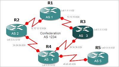
This is feature is used to split an autonomous system into smaller autonomous systems or the reverse which is to combine several autonomous systems into one. Reasons of splitting might be IGP's like OSPF might not be able to handle the routes of a really big enterprise so splitting the AS into smaller will help OSPF scale better, or perhaps the enterprise wants to have separate administrative control per region and wants to control the routing policies on their specific regions. This could also be used if there are company mergers and they want to appear as one AS to other EBGP peers. One thing that intrigues me though is that one of the materials I was using mentioned that this could also be a work around for the BGP Split Horizon Rule. I really doubt that Confederations can be a work around for that. I'll find out for sure in this lab. The diagram below shows 5 Routers with each its own AS number. The goal here to group these routers into one confederation and make them app

EBGP Multihop

Image
Configuring iBGP doesn't require the neighbor address to be directly connected. The best practice for iBGP is to use the loopback address as the ip address configured on the BGP neighbor statement. Loopback interfaces never go down so provided that there is an alternate route to the loopback ip address through an IGP, BGP session will not be torn down. Using loopback addresses for eBGP is also a good practice if there are multiple links between two routers on different autonomous system as shown on the example diagram below. This will also achieve load balancing. The initial configuration for this lab is shown below. R1# ! interface Serial1/0 ip address 10.10.10.1 255.255.255.0 serial restart-delay 0 end ! interface Serial1/1 ip address 10.10.20.1 255.255.255.0 serial restart-delay 0 end ! interface Loopback0 ip address 1.1.1.1 255.255.255.255 ! router bgp 1 no synchronization bgp log-neighbor-changes neighbor 2.2.2.2 remote-as 2 no auto-summary ! ip route 2.2.2.2 255.255.2

BGP MED

Image
BGP MED is an optional non- transitive attribute meaning its not propagated throughout the whole internet but just to adjacent AS. The word "optional" means that this is not necessarily by default sent with the BGP updates. The purpose of MED is to influence how other autonomous systems enter your AS to reach a certain prefix. If the other attributes are set to default, MED will be the attribute used for path selection however, if Weight or Local preference is configured on the adjacent AS router, then MED will not be selected. The lower the MED the more preferred the path will be. Acronym for Multi Exit Discriminator and otherwise known as "Metric" in the BGP table. The lower the MED the more preferred. It is an optional non-transitive attribute. Can dictate how other AS enter your AS. Configure R4 so that it will advertise a MED value of 30 to R3 and 20 to R2. Afterwards, tweak the route map to set a MED of 10 for network 144.144.144.144/32 in R4 towards R3.

BGP Local Preference

Image
  Local Preference is one of the ways to alter the path taken by one AS to reach another AS. The difference between Local Preference and Weight is that Weight is just locally signifant in the router while Local Preference is what I call "Local AS significant". What I mean by that is that Local Preference is being propagated Intra AS but not outside the AS. Local preference is to influence your own AS how to get or exit to another AS. MED is to influence other AS how to enter your AS. The higher the local preference, the more preferred. In this lab, local preference will be configured and will be using route map for more flexibility. Check the diagram below for details. R1, R2 and R3 belongs to AS 123. R4 is in AS4 and is advertising 4.4.4.4/32, 44.44.44.44/32 and 144.144.144.144/32 subnets.We need to set all routes learned from R3 to have local preference value of 300. After which, configure a route-map that will assign a local preference of 500 in R2 for the network 144.1

Cisco Command Summary

Cisco Router Configuration Commands Requirement Cisco Command Set a console password to cisco Router(config)# line con 0 Router(config-line)# login Router(config-line)# password cisco Set a telnet password Router(config)# line vty 0 4 Router(config-line)# login Router(config-line)# password cisco Stop console timing out Router(config)# line con 0 Router(config-line)# exec-timeout 0 0 Set the enable password to cisco Router(config)# enable password cisco Set the enable secret password to peter. This password overrides the enable password and is encypted within the config file Router(config)# enable secret peter Enable an interface Router(config-if)# no shutdown To disable an interface Router(config-if)# shutdown Set the clock rate for a router with a DCE cable to 64K Router(config-if) clock rate 64000 Set a logical bandwidth assignment of 64K to the serial interface Router(config-if) bandwidth 64 Note that the zeroes are not missing To add an IP address to a interface

Catalyst 1900 Password Recovery

This document descripts how to perform a password recovery on the following switches: Cisco Catalyst 1700 Cisco Catalyst 1900 Cisco Catalyst 2100 Cisco Catalyst 2800 Cisco Catalyst 2820 Step-by-Step Procedure Check the boot firmware version number from the Systems Engineering menu. If the firmware is 1.10 or later, the continue through this document. For older firmwares, please contact Cisco to recover the password. Clearing the Password Power-cycle the switch. After POST completes, the following prompt displays: Do you wish to clear the passwords? [Y]es or [N]o: Note: You have ten seconds to respond. If you don't respond within that time, the Management Console Logon screen displays. You cannot change this waiting period. Enter [Y]es to delete the existing password from nonvolatile RAM (NVRAM). Note: If you type [N]o, the existing password remains valid. Assign a password from the switch management interfaces (management console or command line interface (CLI)). Viewi

Catalyst 2900-XL and 3500-XL Password Recovery Procedure

This document describes the password recovery procedure for the Cisco Catalyst 2900-XL and the Cisco Catalyst 3500-XL. Step-by-Step Procedure Attach a terminal or PC with terminal emulation to the console port of the switch. Use the following terminal settings: 9600 baud rate No parity 8 data bits No stop bit Unplug the power cable. Hold down the mode button while reconnecting the power cord to the switch. You can release the mode button a second or two after the LED above port 1x is no longer illuminated. The following instructions appear: The system has been interrupted prior to initializing the flash file system. The following commands will initialize the flash file system, and finish loading the operating system software: flash_init load_helper boot Type flash_init . Type load_helper . Type dir flash: . The switch file system is displayed: Directory of flash: 2 -rwx 843947 Mar 01 1993 00:02:18 C2900XL-h-mz-112.8-SA 4 drwx 3776 Mar 01 1993 01:23:24 html 6

Password Recovery Procedure for the Cisco 1600 Series Router

This document describes the password recovery procedure for the Cisco 1600 series routers. Step-by-Step Procedure Attach a terminal or PC with terminal emulation to the console port of the router. Use the following terminal settings: 9600 baud rate No parity 8 data bits 1 stop bit No flow control Type show version and record the setting of the configuration register; it is usually 0x2102 or 0x102. Note: Do not continue to step 3 until you record the setting of the configuration register. In step 14 of this password recovery procedure, you must reset the configuration register to the setting that you record in this step. Using the power switch, turn off the router and then turn it on. Press Break on the terminal keyboard within 60 seconds of the powerup to put the router into ROMMON. If the break sequence doesn't work, you can try CTRL+BREAK or possibly sending it through an ASCII code. Type confreg 0x2142 at the rommon 1> prompt to boot from Flash without loadi

Practical BGP Security

hi guys this is an intersting DOC on BGP security http://www.renesys.com/tech/notes/WP_BGP_rev6.pdf

Cisco/Juniper Commands

Cisco Command Juniper Command Co-Ordinating Definition show run sh configuration Show running configuration sh ver sh ver Show version show ip interface brief show interface terse displays the status of interfaces configured for IP show interface [intfc] show interfaces [intfc] detail displays the interface configuration, status and statistics. show controller intfc show interfaces intfc extensive displays information about a physical port device show interface | incl (proto|Desc) show interfaces description displays the interface configuration, status and statistics show ip route show route displays summary information about entries in the routing table show ip bgp summary show bgp summary displays the status of all Border Gateway Protocol (BGP) connections show ip bgp net mask show route protocol bgp prefix will show you how that route is being advertised, look for the first line show ip bgp net mask longer-prefixes show route range prefix will show you how that route is