Posts

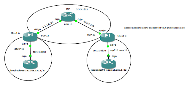
Adding ACLS for allowing access from Client-A LAN to Client-B Lan

Image

network design model

Image

Network design for small scale company

Image

How to Configure DHCP on a Cisco Router or Cisco Switch?

1. Configure an IP address on the router’s Ethernet port, and bring up the interface. Router(config)# interface ethernet0/0 Router(config-if)#ip address 1.1.1.1 255.0.0.0 Router(config-if)# no shutdown 2. Create a DHCP IP address pool for the IP addresses you want to use. Router(config)# ip dhcp pool mypool 3. Specify the network and subnet for the addresses you want to use from the pool. Router(dhcp-config)# network 1.1.1.0 /8 4. Specify the DNS domain name for the clients. Router(dhcp-config)#domain-name mydomain.com 5. Specify the primary and secondary DNS servers. Router(dhcp-config)#dns-server 1.1.1.10 1.1.1.11 6. Specify the default router (i.e., default gateway). Router(dhcp-config)#default-router 1.1.1.1 7. Specify the lease duration for the addresses you’re using from the pool. Router(dhcp-config)#lease 7 8. Exit Pool Configuration Mode . Router(dhcp-config)#exit

Disabling Unneeded Services

Step 1: Configure the Physical Interface Because this lab uses only one router, you will simulate an active FastEthernet connection by activating the interface and applying the no keepalive command to initiate an “always up” state, regardless of the existence of a device at the remote end. Normally, you would not use the no keepalive command on a routed interface, except in special circumstances. In this lab, you will use it only for simulation purposes. Configure the R1 physical interface using the IP address shown in the topology diagram. Use the no keepalive command in interface configuration mode, and then use the no shutdown command to activate the interface. Because you have disabled keepalives, the interface status displays as link state (Layer 1) and line protocols state (Layer 2) “up,” even if it is not connected to an external device. R1(config)# interface fastethernet0/0 R1(config-if)# ip address 192.168.10.1 255.255.255.0 R1(config-if)# no keepalive R1(config-if)# no s...
REVERSE TELNET ON AUX PORT

  Requirement :   Need   to   configure   reverse telnet   via   AUX   port. Connect one router's aux port to another device's console port, and telnet to the router.Use reverse telnet to connect to the other device's console via your aux port   Setup   :   Here's how to set it up. 1.       Connect your router's aux port to another device's console port using a Cisco flat crossover cable. 2.       Telnet to your router, enable, and set the aux port up as follows:   R1#conf t R1(config)# line aux 0 R1(config-line)# modem InOut R1(config-line)# transport preferred all R1(config-line)# transport input all R1(config-line)# transport output all R1(config-line)# end 3.       Make sure you have an address on your lo0 interface, and the interface is up. R1#conf t R1(config)#int   lo0 R1(config-if)#ip   add   127.0.0.1 255.255.255.0 Executio...

Disaster Recovery in Router s

This information is here primarily for my reference at customer sites; for some odd reason, I seem to be recovering IOS images through ROMMON quite a bit lately. These are the minimum fields to get this going through TFTP rather than XModem. Hopefully you find this beneficial as well! rommon 1 > IP_ADDRESS=192.168.1.100 rommon 2 > IP_SUBNET_MASK=255.255.255.0 rommon 3 > DEFAULT_GATEWAY=192.168.1.1 rommon 4 > TFTP_SERVER=192.168.1.50 rommon 5 > TFTP_FILE=c2600-adventerprisek9-mz.124-5a.bin rommon 6 > tftpdnld            (this command kicks off the tftp download)

Completely Clearing a Cisco Switch...The Easy Way!

Clearing out a Cisco switch configuration is always a pain because VLANs are kept in a seperate file from the startup-config (NVRAM). There's two ways to clear a switch back to the factory defaults - the easy way and the REALLY easy way: The easy way - Switch# write erase Switch# delete flash:vlan.dat Switch# reload

OSPF Neighbor Exchange Process

Image
Using the Hello protocol, there is a series of exchanges that routers go through in order to establish relationship when OSPF is initilized. I’d like to go through some of this steps using examples from a lab environment, and watching some debug output in the process. To start, here’s the setup for the exercise: Figure 1: A simple topology Dynamips .net Config: # OSPF Neighbor Exchange Lab Topology autostart = False ghostios = true sparsemem = true [localhost]    [[7200]]         image = \Program Files\Dynamips\images\C7200-JK.BIN         # On Linux / Unix use forward slashes:         # image = /opt/7200-images/c7200-jk9o3s-mz.124-7a.image         npe = npe-400         ram = 96         ghostios = True         [[ROUTER A]]   ...

OSPF LSA's

Type LSA Functionality 1 Router Defines the state and cost of the link to the neighbor and IP prefix associated with the point-to-point link. 2 Network Defines the number of routers attached to the segment. It gives information about the subnet mask on that segment. 3 Summary network Describes the destination outside an area but within the OSPF domain. The summary for one area is flooded into other areas, and vice versa. 4 Summary ASBR Describes the information about the ASBR. In a single area, there will be no summary Type 4 LSA. 5 External Defines routes to destination external to OSPF domain. Every subnet is represented by a single external LSA. 6 [*] Group membership 7 NSSA Defines routes to an external destination, but in a separate LSA format known as Type 7. 8 [*] Unuse...

Non-Routable (Private) IP

RFC 1597 provides for a group of Internet Networks that will never be assigned. Furthermore, these addresses will not route through the Internet. This makes them the proper choice for use in your home or company Intranet. We recommend non-routable IP for most networks. These IP addresses have specifically been set aside to use when it isn’t necessary (or desirable) for anyone on the Internet to be able to instantly navigate to your computer. It is especially useful to the DSL and Cable Modem users who have multiple computers connected to a single proxy server, firewall or router. These non-routable IP addresses also provide additional security on the “Internal” side of your network. Typically a firewall, Cable Modem or DSL router will provide Network Address Translation (NAT) to translate the these nonroutable address to a real Internet routable IP address. Reserved IP addresses for private networks 10.0.0.0 – 10.255.255.255          ...